Qualify the Operation of Steel Flanges using In-Situ ABI® Testing
Qualify the Operation of Steel Flanges using In-Situ ABI® Testing
A company operating an off-shore oil platform required Charpy V-Notch (CVN) values to qualify steel flanges. However, they could not cut samples to perform the destructive testing. The goal of this project was to estimate the Charpy V-Notch (CVN) impact energy at -50°F (-46°C) from in-situ Automated Ball Indentation® (ABI®) tests conducted at room temperature on numerous steel flanges. One spare flange was used to machine nine 0.45T CT fracture toughness specimens to validate the innovative nondestructive methodology for the qualification of 12 flanges before their offshore installation.
TEST PROCEDURES and RESULTS
To assess the acceptability and the structural integrity of the steel flanges per the ASTM requirements and per the API Standard 579 (Recommended Practice for Fitness-for-Service), fracture toughness specimens were tested at room temperature and at three low test temperatures. Six (6) of the 0.45-inch-thick (0.45T) compact tension (CT) specimens failed by cleavage when tested at the test temperatures of -100°F (-73°C) and -148°F (-100°C), and produced a valid Reference Temperature (T0) of -175°F (-115°C) per ASTM Standard Test Method E1921. The multiple ABI® tests conducted on a sample machined from the same flange (of the destructive fracture toughness specimens) produced a reference temperature of -99°F (-73°C). These results show that the T0 determined from the ABI® tests at low temperature is conservative by 42°C for the same steel flange.
In-situ (field) ABI® testing can be conducted only at room/ambient temperature; therefore, four to five ABI® tests were conducted on each flange at room temperature in order to determine a very conservative T0 for each flange. The conservative T0 values were the result of using ductile fracture toughness values (instead of brittle/cleavage values) from room-temperature ABI® tests in the Weibull statistical analysis of the Master Curve Standard E1921. The room-temperature ABI® tests produced T0 values ranging from -30°C (-22°F) to -22°C (-8°F) for all flanges. Per ASTM Standard E1921, and since all T0 values were within 20°C for all twelve (12) flanges, they are considered of the same material, and the average T0 for all flanges can be taken as -26°C. This T0 value of -26°C is very conservative by 89°C (as compared to the T0 of -115°C from the destructive fracture toughness specimens). This is consistent with the results of the PRCI Report L52280 (2007) where 15 ABI® tests conducted at room temperature determined a T0 value of -15°C, i.e. conservative by 71°C [as compared to a valid value from 0.45T CT specimens machined from a carbon steel storage vessel of British Petroleum with T0 of -86°C (Figs. 20 and 22 of PRCI Report L52280)].
The very conservative ABI-determined T0 values of -30°C to -22°C were used in the equation of the fracture toughness master curve to calculate the fracture toughness values at -46°C (-50°F) and these values were then used in Equation F.66 (KIC = 8.47 (CVN) 0.63 for SI units) of API 579-1/ASME FFS-1 2007 “Fitness-For-service” to calculate lower bound estimates of the CVN values for all 12 flanges. The estimated CVN values ranged from 24.6 ft.lb to 28.4 ft.lb (33.6 J to 38.8 J) which are higher than the minimum CVN requirement of 15 ft.lb (20 Joules) at -50°F (-46°C). Hence, all the 12 steel flanges were determined to be fit for offshore service.
The in-situ ABI® tests were conducted using the mobile version of the Stress-Strain Microprobe® (SSM™) system. The load frame of the SSM™ system with a cylindrical magnetic base is shown in Figure 1 testing a flange at the customer’s yard.
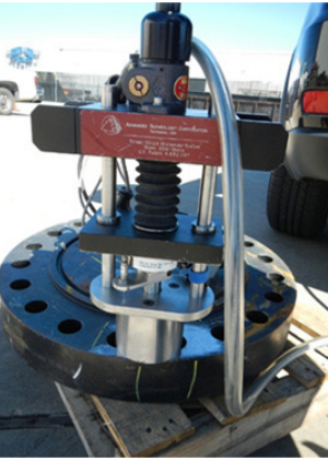
Figure 1 Photo of SSM™-Mobile system testing a steel flange in a yard. The load frame of the SSM system is temporarily mounted on the steel flange using a custom-made small-cylindrical DC magnet.
Fracture Toughness Results:
Nine 0.45T CT specimens were tested at various temperatures (see fracture surfaces in Fig. 2). The load versus COD graphs are shown in Figure 3. The fracture toughness master curve per ASTM E1921 is shown in Figure 4. The reference temperature was determined to be -115°C (-175°F).
The fracture toughness master curve from triplicate ABI® tests conducted at three low temperatures on a sample from the same steel flange (with the results shown in Figure 4) is given in Figure 5.
An example of the fracture toughness master curves from room temperature ABI® tests on three flanges tested at the customer facility is shown in Figure 6.
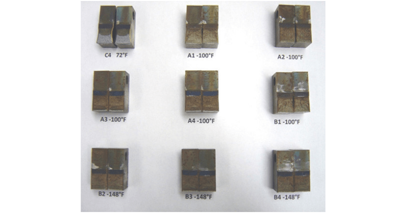
Figure 2 Fracture surfaces of nine 0.45T CT specimens tested at various temperatures (72°F to -148°F).
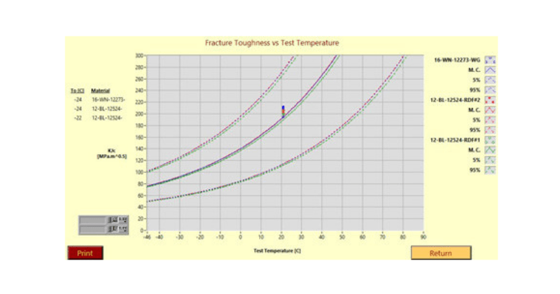
Figure 3 Load versus Crack Opening Displacement (COD) of eight 0.45 CT fracture toughness specimens. Specimens A1 and B1 (blue and black curves) were invalid and not included in the Master Curve of Fig. 4 because they experienced ductile crack growth prior to their cleavage (see Figure 2). Load versus Crack Opening Displacement (COD) of eight 0.45 CT fracture toughness specimens. Specimens A1 and B1 (blue and black curves) were invalid and not included in the Master Curve of Figure 4 because they experienced ductile crack growth prior to their cleavage (see Figure 2).
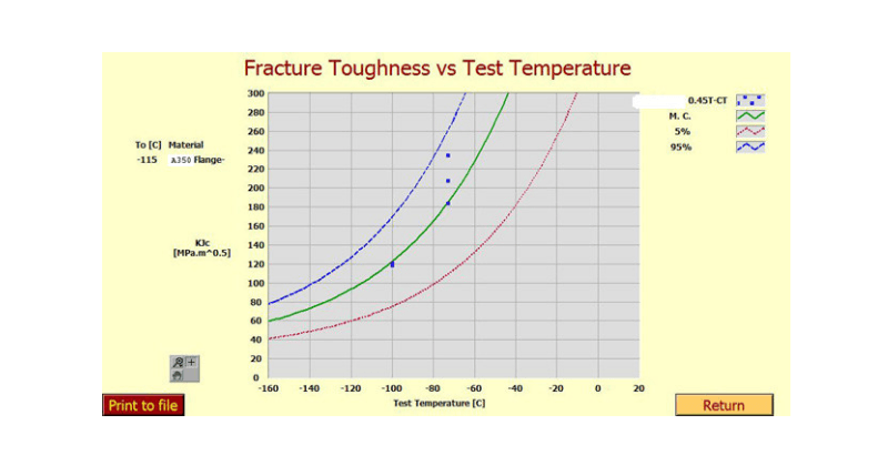
Figure 4 Fracture toughness master curve from valid fracture toughness specimens machined from a spare steel flange.
The Reference Temperature (T0) is the temperature at a median fracture toughness level of 100 MPa√m.
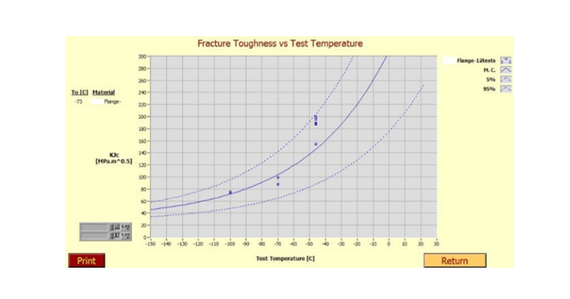
Figure 5 Fracture toughness master curve from ABI® tests conducted at three low test temperatures on a sample cut from the same spare steel flange with 0.4T CT specimens shown earlier in Figure 2

Figure 6 Example of Fracture toughness master curves from room temperature ABI® tests on three steel flanges.
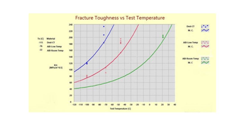
Figure 7 Median Fracture Toughness Master Curves from: (a) destructive fracture toughness specimens (highest/blue curve), (b) from 12 ABI® tests at low test temperatures (middle/red curve), and (c) from in-situ ABI® tests at ambient/room-temperature (lowest/green curve). Note that the lowest/green curve (highest Reference Temperature of -22°C from in-situ ABI® tests at RT) produces the lowest fracture toughness values (and also lowest CVN values) for the same temperature (i.e., drawing a vertical line, e.g. at -70°C produces three levels of fracture toughness values, hence, illustrating the conservatism of the in-situ ABI® tests at RT producing the lowest/green Master Curve).
The ABI® test results and estimation of the CVN values for six flanges are given in Table 1. The other six flanges show similar results.
The methodology for estimating the CVN values is given below.
Median Fracture Toughness Master Curve Equation per ASTM Standard E1921:
KJc = 30 + 70 x e ^0.019 (T-To) (1) [Equation 1]
Where KJc is the median fracture toughness in MPa√m, T is the test temperature in Centigrade, and T0 is the reference temperature at a median fracture level at 100 MPa√m.
All ABI® tests were conducted on the twelve (12) flanges at room temperature. The lowest average fracture toughness value was from Flange “12524-RDF#1”. All ABI® tests met the critical fracture strain model for ductile behavior. For a very conservative estimate of the Reference Temperature (T0), the fracture toughness values (although ductile at room temperature) were used as if they met the critical fracture stress model (for brittle/cleavage behavior). Applying the Master Curve (MC) analysis of ASTM Standard E1921 to the five ABI® tests of Flange 12524-RDF#1 produced a very conservative T0 of -22°C.
Eleven ABI® tests were conducted on a piece cut from the same spare steel flange at the low-test temperatures of -46°C, -73°C, and -100°C (-50°F, -100°F, and -148°F, respectively), and the resultant T0 was -73°C which indicates that the T0 of -22°C from the ABI® tests conducted at room temperature on the same flange piece were conservative by 51°C.
Using the conservative T0 of -22°C from ABI® tests conducted at room temperature (RT) of Flange 12524-RDF#1 in the above MC Equation 1 produces a fracture toughness value of 75.2 MPa√m at the temperature of -46°C (-50°F).
Using the API 579/ASME FFS-1 2007 Fitness-For-Service, Equation F.66 of KIC = 8.47 (CVN) 0.63 for SI units produces an estimated Charpy V-Notch (CVN) Impact Energy of 32 Joules which is higher than the required 20 Joules at -46°C (-50°F). Using the ABI-T0 of -73°C from low test temperatures produces a KJc of 146.9 MPa√m and a CVN estimate of 92.7 Joules.
Finally, determining T0 from 6 valid 0.45T CT specimens tested per E1820 and E1921 standards produced a T0 of -115°C. This is much lower than the T0 from ABI® tests. The estimated CVN value at -46°C (-50°F) from this very low T0 of -115°C is 272.3 Joules.
All twelve flanges meet the CVN requirements of 15 ft-lb at -50°F (-46°C). Hence, they are fit for service at low temperatures (offshore application).
Table 1 ABI® Test Results on six Flanges including Estimation of the CVN Values at -50°F (-46°C)

DISCUSSION
Figure 7 demonstrates the conservatism of using in-situ ABI® tests conducted at ambient/room temperature (RT) to determine a Reference Temperature (T0) and to further estimate Charpy V-Notch (CVN) impact energy at -46°C (-50°F) using the empirical equation F.66 of ASME FFS-1. It can be seen from this figure that the Reference Temperature from the in-situ ABI® tests at RT is higher than that from the ABI® tests at low test temperatures and where the latter is also higher than T0 from valid destructive fracture toughness specimens.
CONCLUSION
The very conservative ABI-determined T0 values of -30°C to -22°C were used to calculate the fracture toughness values at -46°C (-50°F) and these values were then used in Equation F.66 of API 579-1/ASME FFS-1 2007 “Fitness-For-service” to calculate lower bound estimates of the CVN values for all 12 flanges. The estimated CVN values ranged from 24.6 ft.lb to 28.4 ft.lb (33.6 J to 38.8 J) which are higher than the minimum CVN requirement of 15 ft.lb (20 Joules) at -50°F (-46°C). Hence, all 12 steel flanges were determined to be fit for offshore service.
ABOUT THE AUTHOR:
Fahmy Haggag has more than 45 years of experience in the materials engineering field with emphasis on research and development in the areas of fracture mechanics, metallurgy, applied mechanics, miniaturized specimen technology, structural integrity, pipeline infrastructure, and nuclear engineering including radiation damage and reactor safety. His extensive experimental and analytical work resulted in more than 80 publications in the scientific literature. Fahmy is the
inventor of U.S. Patent 4,852,397 ("Field Indentation Microprobe for Structural Integrity Evaluation", 1989) and has held research and development positions at the Oak Ridge National Laboratory (Idaho), National Engineering and Environmental Laboratory, Battelle Columbus Laboratories, University of California at Santa Barbara, Algerian Nuclear Research Center and University of Algiers, and the Egyptian Atomic Energy Authority.